Introduction
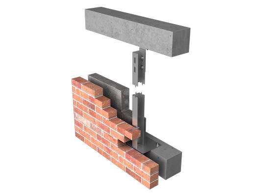
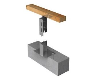
The GA VEW2 range of windposts are of channel section where the post sits in the cavity of the wall, they are generally used for lighter load conditions than the GA VEW1 type posts.
The use of a GA VEW2 Windpost is governed by the size of the cavity and the load to be supported i.e. it may not be possible to increase the section of the post and therefore its load capacity due to the size of the cavity.
In the case of cast stone units the fixing options are increased as cast-in fixings may also be considered.
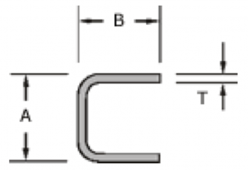
Minimum Channel Sections
| T (mm) | “A” | “B” |
| 4 | 35 | 20 |
| 5 | 35 | 25 |
| 6 | 40 | 35 |
| 8 | 55 | 50 |
| 10 | 90 | 80 |
| 12 | 90 | 80 |
GA WPTC
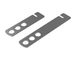
The GA WPTC one way tie is clipped to VEW2 edges to tie into both block and brick courses.
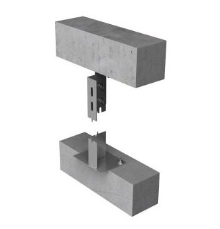
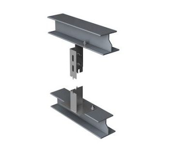
VEW2 WINDPOST CONNECTION EXAMPLES
Performance Tables
Windposts are designed as simply supported beams with a maximum design strength of 230N/mm2 and a maximum deflection of span/360. Design resistances should be compared with factored loads. Recommended loads include a variance factor of 1.5
VEW2 Windposts – Recommended resistance
| Windpost Section Size | Recommended resistance (UDL) kN per post | |||||||
| 2.5m | 3m | 3.5m | 4m | 4.5m | 5m | 5.5m | 6m | |
| 65 x 60 x 4 | 3.25 | 2.3 | 1.74 | 1.35 | ||||
| 65 x 60 x 5 | 3.95 | 2.8 | 2.1 | 1.6 | ||||
| 75 x 60 x 4 | 4.3 | 3.15 | 2.35 | 1.85 | ||||
| 75 x 60 x 5 | 5.4 | 3.86 | 2.9 | 2.25 | 1.75 | |||
| 85 x 60 x 4 | 5.45 | 4.05 | 3.1 | 2.4 | 1.95 | |||
| 85 x 60 x 5 | 6.95 | 5.09 | 3.8 | 2.95 | 2.35 | 1.9 | ||
| 95 x 60 x 5 | 8.6 | 6.35 | 4.85 | 3.8 | 3.05 | 2.45 | 2.05 | |
| 105 x 60 x 5 | 10.3 | 7.75 | 6 | 4.75 | 3.8 | 3.1 | 2.55 | 2.15 |
| 105 x 60 x 6 | 11.1 | 9.05 | 7 | 5.5 | 4.4 | 3.6 | 3 | 2.5 |
| 115 x 60 x 8 | 11.1 | 13.3 | 10.6 | 8.5 | 6.85 | 5.6 | 4.65 | 3.9 |
Bold figures indicate resistance limited by tie capacity / ties required at reduced vertical centres.
VEW2 Windposts – Design resistance
| Windpost Section Size | Design resistance (UDL) kN per post | |||||||
| 2.5m | 3m | 3.5m | 4m | 4.5m | 5m | 5.5m | 6m | |
| 65 x 60 x 4 | 4.88 | 3.45 | 2.61 | 2.03 | ||||
| 65 x 60 x 5 | 5.93 | 4.2 | 3.15 | 2.4 | ||||
| 75 x 60 x 4 | 6.45 | 4.73 | 3.53 | 2.78 | ||||
| 75 x 60 x 5 | 8.1 | 5.79 | 4.35 | 3.38 | 2.63 | |||
| 85 x 60 x 4 | 8.18 | 6.08 | 4.65 | 3.6 | 2.93 | |||
| 85 x 60 x 5 | 10.43 | 7.64 | 5.7 | 4.43 | 3.53 | 2.85 | ||
| 95 x 60 x 5 | 12.9 | 9.53 | 7.28 | 5.7 | 4.58 | 3.68 | 3.08 | |
| 105 x 60 x 5 | 15.45 | 11.63 | 9 | 7.13 | 5.7 | 4.65 | 3.83 | 3.23 |
| 105 x 60 x 6 | 16.65 | 13.58 | 10.5 | 8.25 | 6.6 | 5.4 | 4.5 | 3.75 |
| 115 x 60 x 8 | 16.65 | 19.95 | 15.9 | 12.75 | 10.28 | 8.4 | 6.98 | 5.85 |
Bold figures indicate resistance limited by tie capacity / ties required at reduced vertical centres.

