Introduction
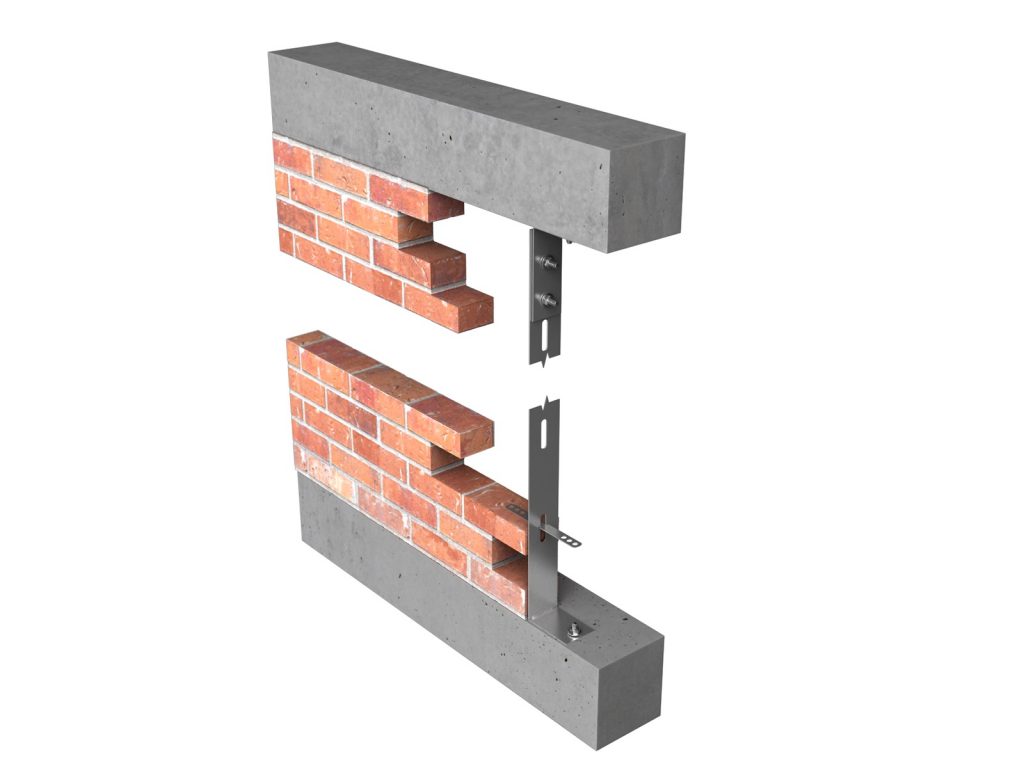
VEW3 Spine Posts add strength and stability to single leaf walls without protruding beyond the width of the blockwork.
In this way, decorative wall surfaces and ‘fair faced’ finishes are possible without compromising on safety.
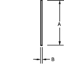
Although the width of VEW3 Spine Posts is limited by the width of the masonry (we recommend they sit within the wall by at least 10mm either side), the thickness of the post itself can be increased to add to its load capacity.
Service
GA undertake the design of the angle section and fixings required and will also produce layout drawings detailing the fixing positions, angle lengths and sectional details for approval prior to manufacture
Once approved, the layout drawings are then marked up to show individual angle references for ease of location and setting out on site.
GA VEW3 Spine Post Properties
The tables below show section properties, recommended resistance loads and design resistance loads for VEW3 Spine Posts acting as simply supported beams. For further information on alternative VEW3 Spine Post sections and loadings for posts designed as propped cantilevers, please contact GA.
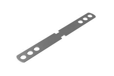
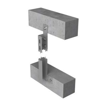
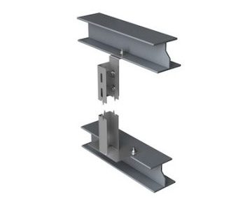
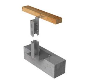
Base plate examples
Performance Tables
Windposts are designed as simply supported beams with a maximum design strength of 230N/mm2 and a maximum deflection of span/360. Design resistances should be compared with factored loads. Recommended loads include a variance factor of 1.5
VEW3 SPINE POSTS – Recommended resistance
| Windpost Section Size | Recommended resistance (UDL) kN per post | |||||||
| 2.5m | 3m | 3.5m | 4m | 4.5m | 5m | 5.5m | 6m | |
| 90 x 8 | 3 | 2.2 | 1.65 | |||||
| 100 x 8 | 3.95 | 2.9 | 2.2 | 1.7 | 1.35 | |||
| 110 x 8 | 5 | 3.75 | 2.9 | 2.25 | 1.8 | 1.45 | ||
| 120 x 8 | 6.25 | 4.75 | 3.7 | 2.9 | 2.35 | 1.9 | 1.6 | 1.35 |
Bold figures indicate resistance limited by tie capacity / ties required at reduced vertical centres.
VEW3 SPINE POSTS – Design resistance
| Windpost Section Size | Design resistance (UDL) kN per post | |||||||
| 2.5m | 3m | 3.5m | 4m | 4.5m | 5m | 5.5m | 6m | |
| 90 x 8 | 4.5 | 3.3 | 2.48 | |||||
| 100 x 8 | 5.93 | 4.35 | 3.3 | 2.55 | 2.03 | |||
| 110 x 8 | 7.5 | 5.63 | 4.35 | 3.38 | 2.7 | 2.18 | ||
| 120 x 8 | 9.38 | 7.13 | 5.55 | 4.35 | 3.53 | 2.85 | 2.4 | 2.03 |
Bold figures indicate resistance limited by tie capacity / ties required at reduced vertical centres.

